一、前言 在實時性要求較高的場合中,CPU軟體執行的方式顯然不能滿足需求,這時需要硬體邏輯實現部分功能。要想使自定義IP核被CPU訪問,就必須帶有匯流排介面。ZYNQ採用AXI BUS實現PS和PL之間的數據交互。本文以PWM為例設計了自定義AXI匯流排IP,來演示如何靈活運用ARM+FPGA的架構。 ...
一、前言
在實時性要求較高的場合中,CPU軟體執行的方式顯然不能滿足需求,這時需要硬體邏輯實現部分功能。要想使自定義IP核被CPU訪問,就必須帶有匯流排介面。ZYNQ採用AXI BUS實現PS和PL之間的數據交互。本文以PWM為例設計了自定義AXI匯流排IP,來演示如何靈活運用ARM+FPGA的架構。
功能定義:在上一篇ZYNQ入門實例博文講解的系統中添加自定義IP核,其輸出驅動LED等實現呼吸燈效果。並且軟體通過配置寄存器方式對其進行使能、打開/關閉配置以及選擇占空比變化步長。另外,可以按鍵操作完成占空比變化步長的增減。
平臺:米聯客 MIZ702N (ZYNQ-7020)
軟體:VIVADO+SDK 2017
註:自定義IP邏輯設計採用明德揚至簡設計法
二、PWM IP設計
PWM無非就是通過控制周期脈衝信號的占空比,也就是改變高電平在一段固定周期內的持續時間來達到控制目的。脈衝周期需要一個計數器來定時,占空比由低變高和由高變低兩種模式同樣需要一個計數器來指示,因此這裡使用兩個嵌套的計數器cnt_cyc和cnt_mode。cnt_mode的加一條件除了要等待cnt_cyc計數完成,還要考慮占空比的變化。
我們可以使用下降沿位置表示占空比,位置越靠近周期值占空比越高。在模式0中下降沿位置按照步長增大直至大於等於周期值,模式1中下降沿位置則按照步長遞減直到小於步長。使用兩個信號up_stage和down_stage分別指示模式0和模式1。至於步長值,在配置有效時被更新,否則使用預設值。模塊最終的輸出信號在周期計數器小於下降沿位置為1,反之為零。設計完畢,上代碼:

  1 `timescale 1ns / 1ps
  2 //////////////////////////////////////////////////////////////////////////////////
  3 // Company:
  4 // Engineer:
  5 //
  6 // Create Date: 2020/03/01 18:14:44
  7 // Design Name:
  8 // Module Name: pwm
  9 // Project Name:
 10 // Target Devices:
 11 // Tool Versions:
 12 // Description:
 13 //
 14 // Dependencies:
 15 //
 16 // Revision:
 17 // Revision 0.01 - File Created
 18 // Additional Comments:
 19 //
 20 //////////////////////////////////////////////////////////////////////////////////
 21
 22
 23 module pwm(
 24 input                       clk,//頻率100MHz 10ns
 25 input                       rst_n,
 26 input                       sw_en,//輸出使能
 27 input                       sw_set_en,//步長設定使能
 28 input       [10-1:0]        sw_freq_step,//步長數值
 29 output reg                  led
 30     );
 31
 32 parameter FREQ_STEP = 10'd100;
 33
 34 parameter CNT_CYC_MAX = 50000;
 35
 36 function integer clogb2 (input integer bit_depth);
 37     begin
 38         for(clogb2=0;bit_depth>0;clogb2=clogb2+1)
 39             bit_depth = bit_depth >> 1;
 40     end
 41 endfunction
 42
 43 localparam CNT_CYC_WIDTH = clogb2(CNT_CYC_MAX-1);
 44
 45
 46 reg [CNT_CYC_WIDTH-1:0] cnt_cyc=0;
 47 wire add_cnt_cyc,end_cnt_cyc;
 48 reg [2-1:0] cnt_mode=0;
 49 wire add_cnt_mode,end_cnt_mode;
 50 wire up_stage,down_stage;
 51 reg [CNT_CYC_WIDTH+1-1:0] neg_loc=0;
 52 reg [10-1:0] freq_step=FREQ_STEP;
 53
 54
 55 //周期計數器 計數50ms=50*1000ns = 50000_0ns
 56 always@(posedge clk)begin
 57     if(~rst_n)begin
 58         cnt_cyc <= 0;
 59     end
 60     else if(add_cnt_cyc)begin
 61         if(end_cnt_cyc)
 62             cnt_cyc <= 0;
 63         else
 64             cnt_cyc <= cnt_cyc + 1'b1;
 65     end
 66 end
 67
 68 assign add_cnt_cyc = sw_en == 1;
 69 assign end_cnt_cyc = add_cnt_cyc && cnt_cyc == CNT_CYC_MAX- 1;
 70
 71 //模式計數器 0-占空比遞增 1-占空比遞減
 72 always@(posedge clk)begin
 73     if(~rst_n)begin
 74         cnt_mode <= 0;
 75     end
 76     else if(add_cnt_mode)begin
 77         if(end_cnt_mode)
 78             cnt_mode <= 0;
 79         else
 80             cnt_mode <= cnt_mode + 1'b1;
 81     end
 82 end
 83
 84 assign add_cnt_mode = end_cnt_cyc && ((up_stage && neg_loc >= CNT_CYC_MAX) || (down_stage && neg_loc == 0));
 85 assign end_cnt_mode = add_cnt_mode && cnt_mode == 2 - 1;
 86
 87
 88 //變化步長設定
 89 always@(posedge clk)begin
 90     if(~rst_n)begin
 91         freq_step <= FREQ_STEP;
 92     end
 93     else if(sw_set_en)begin
 94         if(sw_freq_step >= 1 && sw_freq_step < 2000)
 95             freq_step <= sw_freq_step;
 96         else
 97             freq_step <= FREQ_STEP;
 98     end
 99 end
100
101 //脈衝下降沿對應周期計數器數值
102 always@(posedge clk)begin
103     if(~rst_n)begin
104         neg_loc <= 0;
105     end
106     else if(end_cnt_cyc)begin
107         if(up_stage )begin//占空比遞增階段
108             if(neg_loc < CNT_CYC_MAX)
109                 neg_loc <= neg_loc + freq_step;
110         end
111         else if(down_stage )begin//占空比遞減階段
112             if(neg_loc < freq_step)
113                 neg_loc <= 0;
114             else
115                 neg_loc <= neg_loc - freq_step;
116         end
117     end
118
119 end
120
121 assign up_stage = add_cnt_cyc && cnt_mode == 0;
122 assign down_stage = add_cnt_cyc && cnt_mode == 1;
123
124
125 //輸出
126 always@(posedge clk)begin
127     if(~rst_n)begin
128         led <= 1'b0;//高電平點亮
129     end
130     else if(add_cnt_cyc && cnt_cyc < neg_loc)begin
131         led <= 1'b1;
132     end
133     else
134         led <= 1'b0;
135 end
136
137
138
139 endmodule
pwm.v
VIVADO綜合、佈局佈線比較慢,且軟硬體級聯調試費時費力,所以模擬是極其重要的。編寫一個簡單的testbench,定義update_freq_step task更新步長。這裡使用System Verilog語法有一定的好處。首先單驅動信號可以統一定義為logic變數類型,其次等待時長能指定單位。

 1 `timescale 1ns / 1ps
 2 //////////////////////////////////////////////////////////////////////////////////
 3 // Company:
 4 // Engineer:
 5 //
 6 // Create Date: 2020/03/01 20:49:25
 7 // Design Name:
 8 // Module Name: testbench
 9 // Project Name:
10 // Target Devices:
11 // Tool Versions:
12 // Description:
13 //
14 // Dependencies:
15 //
16 // Revision:
17 // Revision 0.01 - File Created
18 // Additional Comments:
19 //
20 //////////////////////////////////////////////////////////////////////////////////
21
22
23 module testbench();
24
25 logic clk,rst_n;
26 logic sw_en,sw_set_en;
27 logic [10-1:0]sw_freq_step;
28 logic led;
29
30 parameter CYC = 10,
31           RST_TIM = 2;
32
33 defparam dut.CNT_CYC_MAX = 2000;
34
35  pwm#(.FREQ_STEP(100))
36  dut(
37 .clk           (clk) ,//頻率100MHz 10ns
38 .rst_n         (rst_n) ,
39 .sw_en         (sw_en) ,//輸出使能
40 .sw_set_en     (sw_set_en) ,//步長設定使能
41 .sw_freq_step  (sw_freq_step) ,//步長數值
42 .led           (led)
43     );
44
45 initial begin
46     clk = 1;
47     forever begin
48         #(CYC/2.0);
49         clk=~clk;
50     end
51 end
52
53 initial begin
54     rst_n = 1;
55     #1;
56     rst_n = 0;
57     #(RST_TIM*CYC) rst_n = 1;
58 end
59
60 initial begin
61     sw_en = 0;
62     sw_set_en = 0;
63     sw_freq_step = 'd10;
64     #1;
65     #(RST_TIM*CYC);
66     #(CYC*10);
67     sw_en = 1;
68
69     #600us;
70     update_freq_step(50);
71     #600us;
72     $stop;
73
74 end
75
76 task update_freq_step([10-1:0] freq_step);
77     sw_set_en = 1;
78     sw_freq_step = freq_step;
79     #(1*CYC);
80     sw_set_en = 0;
81 endtask
82
83 endmodule
testbench.sv
設計較簡單,直接使用VIVADO模擬器觀察波形即可:

可以看到輸出信號led的占空比在不斷起伏變化,當更新freq_step為50後變化更為減慢。

配置前相鄰兩個neg_loc數值差與更新後分別是100和50。以上證明邏輯功能無誤。
三、硬體系統搭建
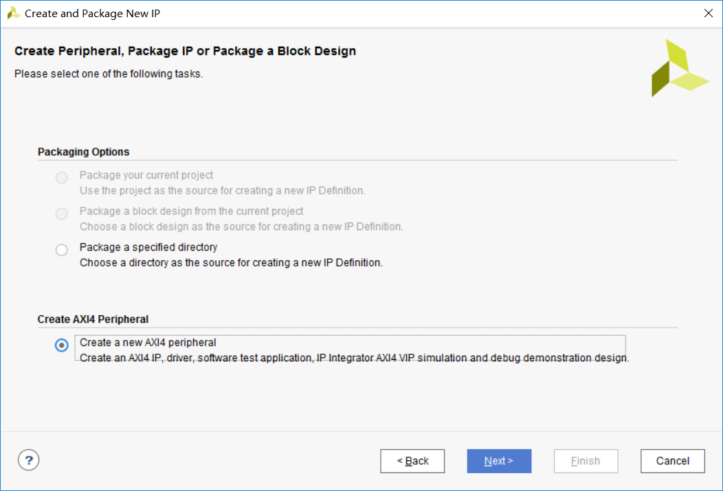
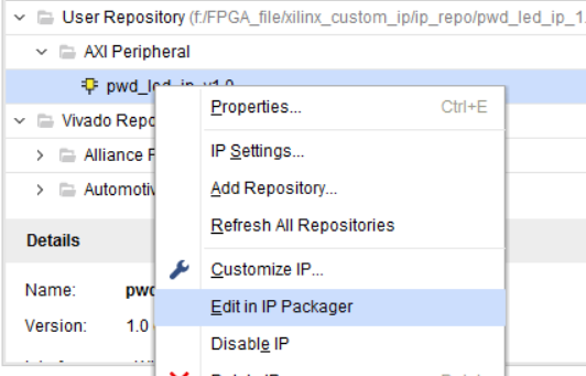
設計完PWM功能模塊還沒有完,需要再包一層匯流排Wrapper才能被CPU訪問。創建AXI匯流排IP

在封裝器中編輯。

最終IP結構如圖:

具體操作不過多講述,直接以代碼呈現:

 1 `timescale 1 ns / 1 ps
 2
 3     module pwm_led_ip_v1_0 #
 4     (
 5         // Users to add parameters here
 6         parameter FREQ_STEP = 10'd100,
 7         // User parameters ends
 8         // Do not modify the parameters beyond this line
 9
10
11         // Parameters of Axi Slave Bus Interface S00_AXI
12         parameter integer C_S00_AXI_DATA_WIDTH    = 32,
13         parameter integer C_S00_AXI_ADDR_WIDTH    = 4
14     )
15     (
16         // Users to add ports here
17         output led,
18         // User ports ends
19         // Do not modify the ports beyond this line
20
21
22         // Ports of Axi Slave Bus Interface S00_AXI
23         input wire  s00_axi_aclk,
24         input wire  s00_axi_aresetn,
25         input wire [C_S00_AXI_ADDR_WIDTH-1 : 0] s00_axi_awaddr,
26         input wire [2 : 0] s00_axi_awprot,
27         input wire  s00_axi_awvalid,
28         output wire  s00_axi_awready,
29         input wire [C_S00_AXI_DATA_WIDTH-1 : 0] s00_axi_wdata,
30         input wire [(C_S00_AXI_DATA_WIDTH/8)-1 : 0] s00_axi_wstrb,
31         input wire  s00_axi_wvalid,
32         output wire  s00_axi_wready,
33         output wire [1 : 0] s00_axi_bresp,
34         output wire  s00_axi_bvalid,
35         input wire  s00_axi_bready,
36         input wire [C_S00_AXI_ADDR_WIDTH-1 : 0] s00_axi_araddr,
37         input wire [2 : 0] s00_axi_arprot,
38         input wire  s00_axi_arvalid,
39         output wire  s00_axi_arready,
40         output wire [C_S00_AXI_DATA_WIDTH-1 : 0] s00_axi_rdata,
41         output wire [1 : 0] s00_axi_rresp,
42         output wire  s00_axi_rvalid,
43         input wire  s00_axi_rready
44     );
45 // Instantiation of Axi Bus Interface S00_AXI
46     pwd_led_ip_v1_0_S00_AXI # (
47         .C_S_AXI_DATA_WIDTH(C_S00_AXI_DATA_WIDTH),
48         .C_S_AXI_ADDR_WIDTH(C_S00_AXI_ADDR_WIDTH),
49         .FREQ_STEP(FREQ_STEP)
50     ) pwd_led_ip_v1_0_S00_AXI_inst (
51         .S_AXI_ACLK(s00_axi_aclk),
52         .S_AXI_ARESETN(s00_axi_aresetn),
53         .S_AXI_AWADDR(s00_axi_awaddr),
54         .S_AXI_AWPROT(s00_axi_awprot),
55         .S_AXI_AWVALID(s00_axi_awvalid),
56         .S_AXI_AWREADY(s00_axi_awready),
57         .S_AXI_WDATA(s00_axi_wdata),
58         .S_AXI_WSTRB(s00_axi_wstrb),
59         .S_AXI_WVALID(s00_axi_wvalid),
60         .S_AXI_WREADY(s00_axi_wready),
61         .S_AXI_BRESP(s00_axi_bresp),
62         .S_AXI_BVALID(s00_axi_bvalid),
63         .S_AXI_BREADY(s00_axi_bready),
64         .S_AXI_ARADDR(s00_axi_araddr),
65         .S_AXI_ARPROT(s00_axi_arprot),
66         .S_AXI_ARVALID(s00_axi_arvalid),
67         .S_AXI_ARREADY(s00_axi_arready),
68         .S_AXI_RDATA(s00_axi_rdata),
69         .S_AXI_RRESP(s00_axi_rresp),
70         .S_AXI_RVALID(s00_axi_rvalid),
71         .S_AXI_RREADY(s00_axi_rready),
72
73         .led(led)
74     );
75
76     // Add user logic here
77
78     // User logic ends
79
80     endmodule
pwm_led_ip_v1_0.v

  1 `timescale 1 ns / 1 ps
  2
  3     module pwm_led_ip_v1_0_S00_AXI #
  4     (
  5         // Users to add parameters here
  6         parameter FREQ_STEP = 10'd100,
  7         // User parameters ends
  8         // Do not modify the parameters beyond this line
  9
 10         // Width of S_AXI data bus
 11         parameter integer C_S_AXI_DATA_WIDTH    = 32,
 12         // Width of S_AXI address bus
 13         parameter integer C_S_AXI_ADDR_WIDTH    = 4
 14     )
 15     (
 16         // Users to add ports here
 17         output led,
 18         // User ports ends
 19         // Do not modify the ports beyond this line
 20
 21         // Global Clock Signal
 22         input wire  S_AXI_ACLK,
 23         // Global Reset Signal. This Signal is Active LOW
 24         input wire  S_AXI_ARESETN,
 25         // Write address (issued by master, acceped by Slave)
 26         input wire [C_S_AXI_ADDR_WIDTH-1 : 0] S_AXI_AWADDR,
 27         // Write channel Protection type. This signal indicates the
 28             // privilege and security level of the transaction, and whether
 29             // the transaction is a data access or an instruction access.
 30         input wire [2 : 0] S_AXI_AWPROT,
 31         // Write address valid. This signal indicates that the master signaling
 32             // valid write address and control information.
 33         input wire  S_AXI_AWVALID,
 34         // Write address ready. This signal indicates that the slave is ready
 35             // to accept an address and associated control signals.
 36         output wire  S_AXI_AWREADY,
 37         // Write data (issued by master, acceped by Slave)
 38         input wire [C_S_AXI_DATA_WIDTH-1 : 0] S_AXI_WDATA,
 39         // Write strobes. This signal indicates which byte lanes hold
 40             // valid data. There is one write strobe bit for each eight
 41             // bits of the write data bus.
 42         input wire [(C_S_AXI_DATA_WIDTH/8)-1 : 0] S_AXI_WSTRB,
 43         // Write valid. This signal indicates that valid write
 44             // data and strobes are available.
 45         input wire  S_AXI_WVALID,
 46         // Write ready. This signal indicates that the slave
 47             // can accept the write data.
 48         output wire  S_AXI_WREADY,
 49         // Write response. This signal indicates the status
 50             // of the write transaction.
 51         output wire [1 : 0] S_AXI_BRESP,
 52         // Write response valid. This signal indicates that the channel
 53             // is signaling a valid write response.
 54         output wire  S_AXI_BVALID,
 55         // Response ready. This signal indicates that the master
 56             // can accept a write response.
 57         input wire  S_AXI_BREADY,
 58         // Read address (issued by master, acceped by Slave)
 59         input wire [C_S_AXI_ADDR_WIDTH-1 : 0] S_AXI_ARADDR,
 60         // Protection type. This signal indicates the privilege
 61             // and security level of the transaction, and whether the
 62             // transaction is a data access or an instruction access.
 63         input wire [2 : 0] S_AXI_ARPROT,
 64         // Read address valid. This signal indicates that the channel
 65             // is signaling valid read address and control information.
 66         input wire  S_AXI_ARVALID,
 67         // Read address ready. This signal indicates that the slave is
 68             // ready to accept an address and associated control signals.
 69         output wire  S_AXI_ARREADY,
 70         // Read data (issued by slave)
 71         output wire [C_S_AXI_DATA_WIDTH-1 : 0] S_AXI_RDATA,
 72         // Read response. This signal indicates the status of the
 73             // read transfer.
 74         output wire [1 : 0] S_AXI_RRESP,
 75         // Read valid. This signal indicates that the channel is
 76             // signaling the required read data.
 77         output wire  S_AXI_RVALID,
 78         // Read ready. This signal indicates that the master can
 79             // accept the read data and response information.
 80         input wire  S_AXI_RREADY
 81     );
 82
 83     // AXI4LITE signals
 84     reg [C_S_AXI_ADDR_WIDTH-1 : 0]     axi_awaddr;
 85     reg      axi_awready;
 86     reg      axi_wready;
 87     reg [1 : 0]     axi_bresp;
 88     reg      axi_bvalid;
 89     reg [C_S_AXI_ADDR_WIDTH-1 : 0]     axi_araddr;
 90     reg      axi_arready;
 91     reg [C_S_AXI_DATA_WIDTH-1 : 0]     axi_rdata;
 92     reg [1 : 0]     axi_rresp;
 93     reg      axi_rvalid;
 94
 95     // Example-specific design signals
 96     // local parameter for addressing 32 bit / 64 bit C_S_AXI_DATA_WIDTH
 97     // ADDR_LSB is used for addressing 32/64 bit registers/memories
 98     // ADDR_LSB = 2 for 32 bits (n downto 2)
 99     // ADDR_LSB = 3 for 64 bits (n downto 3)
100     localparam integer ADDR_LSB = (C_S_AXI_DATA_WIDTH/32) + 1;
101     localparam integer OPT_MEM_ADDR_BITS = 1;
102     //----------------------------------------------
103     //-- Signals for user logic register space example
104     //------------------------------------------------
105     //-- Number of Slave Registers 4


